
FIELD TROUBLESHOOTING / FREQUENTLY ASKED QUESTIONS Troubleshooting 2nd RF Harmonics AM500A | AM1A | AM2.5E | AM5E | AM6A | AM10A |
|

|
|
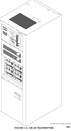
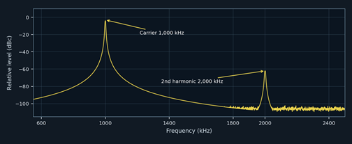
AM-5E drawing • BE manual 597-1114 | Illustrative spectrum trace (not station test data) |
FIRST CHECK: THERMALLY STRESSED MODULATOR & RF MODULE ELECTROLYTICS
Field experience shows that electrolytics mounted in the hot modulator and RF power-module assemblies can dry out, develop high ESR, and crack or split. Inspect these early, particularly if the second RF harmonic has increased with age, heat, or operating power.
1 | What is the second RF harmonic? An RF emission at twice the carrier frequency. A 1,000 kHz station has a second RF harmonic at 2,000 kHz - not a 2 kHz audio harmonic. |
2 | Where should I look first? Modulator 330 µF capacitors, the smaller modulator-board electrolytics, and PA-board electrolytics. Look for heat discoloration, splits, leaks, dried seals, and high ESR. See the detailed parts list on page 2. |
3 | What if the electrolytics look normal? Dried-out capacitors often have no visible damage. Measure capacitance, ESR and leakage with the board made safe; compare suspect parts or known-good modules and check DC/PWM stability. |
4 | When should I check the output harmonic filter? Also check L1-L3, C1-C4, RF connections and frequency kit. A spur high with no modulation - especially if it changes with load or tuning - calls for close examination of PA switching and the RF filter. |
5 | How do I confirm the harmonic is real? Sample with a rated coupler/attenuator and measure carrier versus 2× carrier in dBc. Add analyzer attenuation and verify the ratio stays constant; compare no audio, normal modulation, and a proper 50-ohm test load. |
Safety: Never connect an analyzer directly to transmitter RF output. De-energize, lock out, and discharge stored energy before inspecting modulator or PA assemblies. |
SERVICE PARTS / HEAT-RELATED ELECTROLYTIC FAILURES Modulator & PA Electrolytics High-priority field checks | BE part numbers from factory parts lists |
|

Common failure mode: RF module heat accelerates electrolyte loss. Capacitors may show cracked or split sleeves/cases, swelling, dried seals or leakage - or may test poorly with no visible damage. Check the hottest assemblies first; a bad capacitor can disrupt switching/drive and increase RF harmonic content. |
1 MODULATOR AND LARGE ENERGY-STORAGE ELECTROLYTICS
Assembly / model | Reference | Type & rating | BE part # |
AM1A / AM500A cap boards | C1-C4 on each of 2 boards | 330 µF / 200 V | 013-3385-200 |
AM2.5E / AM5E mod. 917-0302 | C5, C8 (per module) | 330 µF / 200 V | 013-3385-201 |
AM6A / AM10A mod. 917-0302 | C5, C8 (per module) | 330 µF / 200 V | 013-3385-201 |
AM1A mod. 917-0302-102 | C1,C18,C19,C22,C24,C28-C32,C35,C40 | 10 µF / 50 V | 023-1076 |
AM-A / AM-E modulator* | C3,C23,C25 | 22 µF / check voltage** | 024-2274 |
AM-A / AM-E modulator* | C34 | 47 µF / 35 V | 020-4773 |
AM-A / AM-E modulator* | C41 | 33 µF / 25 V NP | 020-3374 |
*Shared designators/part numbers in the referenced legacy schematics; verify each installed board revision. **The same 024-2274 P/N is shown as 22 µF / 100 V in AM1A Rev C and 22 µF / 50 V in older AM-E lists. Confirm rating before replacement.
2 RF POWER AMPLIFIER BOARD - 917-0304
Capacitors (per PA board) | Type & rating | BE part # | Circuit area (general) |
C13 | 100 µF / 63 V | 015-1084 | Supply / local energy storage |
C10 | 100 µF / 35 V | 023-1084 | Supply / control filtering |
C24,C25,C33,C59 | 10 µF / 50 V | 023-1076 | PA control / drive filtering |
C40-C43 | 1 µF / 50 V | 024-1064 | PA control / local circuits |
These electrolytic references are listed for the 917-0304 PA board in the AM-E and AM6A/AM10A parts manuals. A typical RF power module uses two PA boards; verify actual module count and revision.
3 WHAT TO DO WITH A SUSPECT MODULE
Inspect: Look closely around heat-generating components for cracked cans or sleeves, venting, dried seals, leakage, discolored PCB and failing solder joints.
Test: After safe discharge, measure capacitance and ESR; evaluate ripple, DC rails and PWM/PA drive under approved test procedures. A capacitance reading alone may miss a high-ESR failure.
Replace: Match capacitance, polarity, voltage, temperature and ripple-current/ESR requirements. Do not substitute a generic electrolytic solely by µF and volts; confirm the BE board revision.
Sources: BE 597-1112 Rev C, 597-1114 (AM2.5E/AM5E), 597-1113 (AM6A/AM10A legacy parts lists).
FACTORY SERVICE REFERENCE / OUTPUT HARMONIC FILTER RF Filter Capacitors & BE P/Ns Mica capacitors, not electrolytics | Values depend on operating frequency and model |
|

Harmonic filter: actual AM-2.5E schematic excerpt

Manual 597-1114, output-network schematic: L1-L3 and C1-C4 (C5 is in the matching network).
AM1A • output network (single C1 and C3)
Band (kHz) | C1 & C3 (each) | C2 | C4 |
522–650 | 5100 pF | 3300 pF | 8200 pF |
651–770 | 4300 pF | 2700 pF | 6800 pF |
771–920 | 3600 pF | 2200 pF | 5600 pF |
921–1080 | 3300 pF | 1800 pF | 4700 pF |
1081–1300 | 2700 pF | 1600 pF | 3900 pF |
1301–1580 | 2200 pF | 1300 pF | 3300 pF |
1581–1705 | 1800 pF | 1100 pF | 2700 pF |
AM2.5E • output network (single C1 and C3)
Band (kHz) | C1 & C3 (each) | C2 | C4 |
522–650 | 5100 pF | 3300 pF | 8200 pF |
651–770 | 4300 pF | 2700 pF | 6800 pF |
771–920 | 3600 pF | 2200 pF | 5600 pF |
921–1080 | 3300 pF | 2000 pF | 4700 pF |
1081–1300 | 2700 pF | 1600 pF | 3900 pF |
1301–1580 | 2200 pF | 1300 pF | 3300 pF |
1581–1705 | 1800 pF | 1100 pF | 2700 pF |
AM5E • paired C1A/C1B and C3A/C3B (each capacitor shown)
Band (kHz) | C1A/B & C3A/B (each) | C2 | C4 |
522–650 | 2700 pF | 3300 pF | 8200 pF |
651–770 | 2200 pF | 2700 pF | 6800 pF |
771–920 | 1800 pF | 2200 pF | 5600 pF |
921–1080 | 1600 pF | 2000 pF | 4700 pF |
1081–1300 | 1300 pF | 1600 pF | 3900 pF |
1301–1580 | 1100 pF | 1200 pF | 3300 pF |
1581–1705 | 910 pF | 1100 pF | 2700 pF |
Parts from BE 597-1112 Rev C §6.2 and 597-1114 output-network parts tables 3-9–3-22.
SERVICE REFERENCE / MODEL VARIANTS & ELECTROLYTICS Other Models & Parts Checklist Confirm actual frequency kit and revision before ordering or replacing components |
|

AM6A & AM10A: output-network frequency-dependent kit P/Ns
Band (kHz) | AM6A output kit | AM10A output kit |
522–650 | 957-1035-061 | 957-1035-101 |
651–770 | 957-1035-062 | 957-1035-102 |
771–920 | 957-1035-063 | 957-1035-103 |
921–1080 | 957-1035-064 | 957-1035-104 |
1081–1300 | 957-1035-065 | 957-1035-105 |
1301–1580 | 957-1035-066 | 957-1035-106 |
1581–1705 | 957-1035-067 | 957-1035-107 |
Example: 921–1080 kHz RF output mica parts (AM6A / AM10A)
Designator | AM6A | AM10A |
C1A / C1B and C3A / C3B | 6A: each 1600 pF / 044-1623-292 | 10A: C1 value conflicts with its listed P/N* |
C2 / C2A–C2B | 6A: C2 2000 pF / 044-2023-293 | 10A: C2A/B each 910 pF / 044-9113-293 |
C3A / C3B | 6A: included above | 10A: each 1600 pF / 044-1623-293 |
C4 | 6A: 4700 pF / 044-4723-291 | 10A: 4700 pF / 044-4723-293 |
*Manual discrepancy: 1999 AM10A parts table 3-13 prints “4300 pF” for C1A/B but lists BE P/N 044-1823-293. Do not order C1A/B by this entry without confirming the installed part/revision.
ADDITIONAL EXCITER / PWM ELECTROLYTIC REFERENCE
Assembly | Reference designators | Type / rating | BE part # |
ECU exciter 917-0300 | C1,C2,C16,C17 | 10 µF / 50 V NP | 023-1075 |
ECU exciter 917-0300 | C13,C146 | 33 µF / 25 V NP | 020-3374 |
ECU exciter 917-0300 | C83,C89,C125,C167,C171,C172 | 1 µF / 50 V NP | 020-1064 |
ECU exciter 917-0300 | C174 | 2.2 µF / 50 V NP | 020-2264 |
ECU exciter 917-0300 | C32,C54,C61,C62,C69,C70,C93,C118,C121,C140 | 10 µF / 50 V polar | 023-1076 |
ECU exciter 917-0300 | C34,C36,C94,C105,C106 | 22 µF / see note | 024-2274 |
ECU exciter 917-0300 | C71,C72 | 100 µF / 35 V polar | 023-1084 |
A1A modulator 917-0302-102 | C41; C34 | 33 µF/25 V NP; 47 µF/35 V | 020-3374; 020-4773 |
A1A modulator 917-0302-102 | C1,C18,C19,C22,C24,C28–C32,C35,C40 | 10 µF / 50 V polar | 023-1076 |
A1A modulator 917-0302-102 | C3,C23,C25 | 22 µF / see note | 024-2274 |
AM1A mod. cap boards (2) | C1–C4 on each board (8 total) | 330 µF / 200 V | 013-3385-200 |
AM2.5E/5E mod. 917-0302 | C5,C8 (per module) | 330 µF / 200 V | 013-3385-201 |
NP = nonpolarized; “polar” = polarized electrolytic. 22 µF voltage-rating conflict: the older AM-E manual lists 50 V and AM1A Rev C lists 100 V for P/N 024-2274; verify the board/installed voltage rating before replacement. The E-series also uses the other exciter and modulator electrolytics above; revision and board layout may differ.
Sources: BE 597-1112 Rev C (AM500A/AM1A); BE 597-1114 (AM2.5E/AM5E); BE 597-1113 (AM6A/AM10A 1999 parts tables and Rev E, May 2026, operating theory). Manual diagrams credited to Broadcast Electronics.
Heat-stressed modulator and PA board electrolytics: priority checklist on page 2.